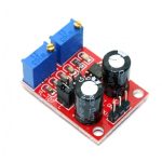
NE555 Pulse Frequency Duty Cycle Adjustable Module Square Wave Signal Generator
Main chip: NE555
1.Input Voltage: 5V-15VDC. when power supply is 5V , the output current can be 15MA around;when 12V
power supply, the output current can 35MA around;
2.Input current: >=100MA;
3.Output amplitude: 4.2V V-PP to 11.4V V-PP. (Different input voltage, the output amplitude will be different)
4.Maximum output current: >=15MA (5V power supply, V-PP greater than 50%), >=35MA (12V power
supply, V-PP greater than 50%)
4.Output with LED indication(low level ,LED will on; high level,LED will off;low frequency, the LED flashes);
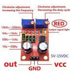
5.The output requency range is selectable:
LF file: 1Hz ~ 50Hz IF file: 50Hz ~ 1kHz
High-frequency file: 1KHz ~ 10kHz
HF file: 10kHz ~ 200kHz
6.Cycle T=0.7 (RA+2RB) C (RA, RB for 0-10K adjustable);
Low frequency:C=100UF; Intermediate frequency:C=1UF;
M-H frequency: C=0.1UF; High frequency: C=0.001UF,
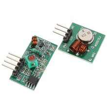
The RF receiver modules are widely used for data receiving and signal control. They are specified as preferred components in remote control garage, roller curtain, door locks, remote sensing, telemetry, industrial control and wireless security alarm industry.
Fixed turn the lamp current to 0.1 times the value of the constant current (charge when used to identify whether the battery is full);
2. Increased input reverse polarity protection diode;
3. Using dedicated reference IC, and high-precision sampling resistor, so that the constant current is more stable, (20 degrees to 100 degrees, the constant current 1A, when the temperature drift of less than 1%).Particularly suitable for LED driver
*High-power LED constant current drive
*Lithium battery charger (including ferroelectric)
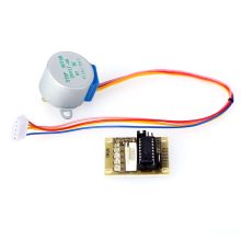
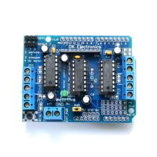
Motor Drive Shield L293D for Arduino Duemilanove Mega / UNO
4-channel DC motor drives, stepper motor or 2 while driving two servos, You can mix:
DC motor driver quad and two steering gear
Drive two DC motor and stepper motor all the way and two-way steering gear
Drive two stepper motors and two servos
Brand new & high quality
Breadboard power supply module, compatible with 5 V, 3.3 V
Apply to MB102 breadboard
Input voltage: 6.5-12 V (DC) or USB power supply
Output voltage: 3.3V/5V can switch over
Maximum output current: <700 ma
Fluctuation two road independent control, can switch over to 0 V, 3.3 V, 5 V
Product Description: NE555 Pulse Frequency Duty Cycle Adjustable Module Square Wave Signal Generator Description: The 555 timer IC is an integrated circuit that is popular used in a variety of timer, pulse generation, and oscillator applications. This NE555 frequency adjustable pulse generator Module utilizes the NE555 timer IC to generate pulses from about 4Hz to 1.3Khz, which can be used for experimental development, or driving a stepper motor, it would be also a good choice for users learning& experiencing the analog RC circuits. There are 4 jumpers and 2 variable resistors on the module, users can adjust the output wave with these components, to get their ideal wave easily. Spescification: Main chip: NE555 1.Input Voltage: 5V-15VDC. when power supply is 5V , the output current can be 15MA around;when 12V power supply, the output current can 35MA around; 2.Input current: >=100MA; 3.Output amplitude: 4.2V V-PP to 11.4V V-PP. (Different input voltage, the output amplitude will be different) 4.Maximum output current: >=15MA (5V power supply, V-PP greater than 50%), >=35MA (12V power supply, V-PP greater than 50%) 4.Output with LED indication(low level ,LED will on; high level,LED will off;low frequency, the LED flashes); 5.The output requency range is selectable: LF file: 1Hz ~ 50Hz IF file: 50Hz ~ 1kHz High-frequency file: 1KHz ~ 10kHz HF file: 10kHz ~ 200kHz 6.Cycle T=0.7 (RA+2RB) C (RA, RB for 0-10K adjustable); Low frequency:C=100UF; Intermediate frequency:C=1UF; M-H frequency: C=0.1UF; High frequency: C=0.001UF, Application: 1. Used as a square wave signal generator, offer the square wave signal for the use of the experimental development. 2. Used to produce driving stepper motor drives, offer the square wave signal. 3. Adjustable pulse for the use of MCU. 4. Generate adjustable pulse control circuit. Package included: 1x NE555 Pulse Frequency Duty Cycle Adjustable Module
Reviews (0)
Reviews
There are no reviews yet.
Be the first to review “NE555 Pulse Frequency Duty Cycle Adjustable Module Square Wave Signal Generator” Cancel reply
Product Description: NE555 Pulse Frequency Duty Cycle Adjustable Module Square Wave Signal Generator Description: The 555 timer IC is an integrated circuit that is popular used in a variety of timer, pulse generation, and oscillator applications. This NE555 frequency adjustable pulse generator Module utilizes the NE555 timer IC to generate pulses from about 4Hz to 1.3Khz, which can be used for experimental development, or driving a stepper motor, it would be also a good choice for users learning& experiencing the analog RC circuits. There are 4 jumpers and 2 variable resistors on the module, users can adjust the output wave with these components, to get their ideal wave easily. Spescification: Main chip: NE555 1.Input Voltage: 5V-15VDC. when power supply is 5V , the output current can be 15MA around;when 12V power supply, the output current can 35MA around; 2.Input current: >=100MA; 3.Output amplitude: 4.2V V-PP to 11.4V V-PP. (Different input voltage, the output amplitude will be different) 4.Maximum output current: >=15MA (5V power supply, V-PP greater than 50%), >=35MA (12V power supply, V-PP greater than 50%) 4.Output with LED indication(low level ,LED will on; high level,LED will off;low frequency, the LED flashes); 5.The output requency range is selectable: LF file: 1Hz ~ 50Hz IF file: 50Hz ~ 1kHz High-frequency file: 1KHz ~ 10kHz HF file: 10kHz ~ 200kHz 6.Cycle T=0.7 (RA+2RB) C (RA, RB for 0-10K adjustable); Low frequency:C=100UF; Intermediate frequency:C=1UF; M-H frequency: C=0.1UF; High frequency: C=0.001UF, Application: 1. Used as a square wave signal generator, offer the square wave signal for the use of the experimental development. 2. Used to produce driving stepper motor drives, offer the square wave signal. 3. Adjustable pulse for the use of MCU. 4. Generate adjustable pulse control circuit. Package included: 1x NE555 Pulse Frequency Duty Cycle Adjustable Module
 Car Vehicle Bike Tools and Accessories


Reviews
There are no reviews yet.